Sensor Integrating Machine Elements: Difference between revisions
| Line 21: | Line 21: | ||
==== Rolling bearing ==== | ==== Rolling bearing ==== | ||
Rolling bearings play a central role in the world of machine elements. These inconspicuous yet extremely vital components are indispensable in a wide range of industrial applications, whether in automotive drive systems, wind turbines, huge turbines in power plants or in the precise mechanisms of state-of-the-art robot technology. Rolling bearings enable low-friction movement and transmit forces efficiently, making a significant contribution to the performance and reliability of a wide range of machines. | |||
As digitalization progresses, the integration of digital technologies in a rolling bearing opens up new possibilities for monitoring and optimization. By implementing condition monitoring systems, data can be collected, analyzed and interpreted during operation to monitor the condition of a rolling bearing in real time. | |||
These systems use a variety of sensors to record parameters such as temperature, vibration, lubricant condition and load. In particular, the use of thin-film sensors on the bearing disk of a rolling bearing can be used to detect temperatures or acting forces directly in the effective zone of the bearing. The collected data is then evaluated using algorithms and analysis techniques to detect potential anomalies or deviations from normal operation at an early stage. This allows maintenance intervals to be optimized, downtimes to be minimized and preventive maintenance measures to be planned. | |||
The condition monitoring of rolling bearings is therefore a key element in the predictive maintenance of machines and systems. It enables a proactive approach to maintenance by providing operators and engineers with important insights into the current condition of the bearings. By detecting wear, damage or other problems in good time, expensive repairs can be avoided and the service life of the machines can be extended. In an increasingly digitalized world, condition monitoring therefore plays a crucial role in ensuring the efficiency, reliability and cost-effectiveness of industrial processes. | |||
==== Gas foil bearing ==== | ==== Gas foil bearing ==== | ||
Revision as of 13:36, 29 February 2024
Your first time working with this wiki? Please read Getting started first!
Interaction of sensor system and machine element
Exemplary measurement tasks in machine elements
Gear
Screw
As one of the most widely used machine elements, the screw offers excellent potential for driving digitalisation through the procurement of data. Therefore, in addition to recording physical quantities that are directly related to the primary function, it is also possible to record a range of other physical quantities. The physical quantities relevant for the primary function are:
- axial force
- torque
- bending torque
Other physical quantities that can be recorded include:
- temperature
- acceleration
- rotational speed
- electric field
- magnetic field
Rolling bearing
Rolling bearings play a central role in the world of machine elements. These inconspicuous yet extremely vital components are indispensable in a wide range of industrial applications, whether in automotive drive systems, wind turbines, huge turbines in power plants or in the precise mechanisms of state-of-the-art robot technology. Rolling bearings enable low-friction movement and transmit forces efficiently, making a significant contribution to the performance and reliability of a wide range of machines.
As digitalization progresses, the integration of digital technologies in a rolling bearing opens up new possibilities for monitoring and optimization. By implementing condition monitoring systems, data can be collected, analyzed and interpreted during operation to monitor the condition of a rolling bearing in real time.
These systems use a variety of sensors to record parameters such as temperature, vibration, lubricant condition and load. In particular, the use of thin-film sensors on the bearing disk of a rolling bearing can be used to detect temperatures or acting forces directly in the effective zone of the bearing. The collected data is then evaluated using algorithms and analysis techniques to detect potential anomalies or deviations from normal operation at an early stage. This allows maintenance intervals to be optimized, downtimes to be minimized and preventive maintenance measures to be planned.
The condition monitoring of rolling bearings is therefore a key element in the predictive maintenance of machines and systems. It enables a proactive approach to maintenance by providing operators and engineers with important insights into the current condition of the bearings. By detecting wear, damage or other problems in good time, expensive repairs can be avoided and the service life of the machines can be extended. In an increasingly digitalized world, condition monitoring therefore plays a crucial role in ensuring the efficiency, reliability and cost-effectiveness of industrial processes.
Gas foil bearing
Journal bearing
Shaft coupling
Splined shaft
Key
Seal
Calculation methodology for service life / load carrying capacity
Evaluation method for load carrying capacity
Mechanical integration
Prototypes
Components
Wiring / connectors
Testing / validation
Requirements for test technology
Validation strategy
Cost aspects
Potentials / challenges additive manufacturing
Potentials / challenges heat treatment
Operating strategy
Data handling
Algorithms for reduction
Methods for buffering
Outlook on the use of data
Operating strategy for processors
Validation strategy
Data transfer
Barriers / shielding
Protocols
Microsystem technology
Sensor systems
Overview of physical measuring principles
Temperature
Strain
Acceleration
Acoustic noise
Conductivity / impedance
Resilience
Energy harvesters
Energy storages
Processors (in situ)
Methodology for design of SiME
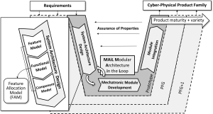
SiME können durch ihre mechanischen, elektrischen und informationstechnischen Komponenten als mechatronische bzw, Cyber-Physische Systeme (CPS) verstanden werden. Die Entwicklung von mechatronischen Systemen kann methodisch unterstützt werden. Die VDI-Richtlinie VDI2206 zum Entwurf mechatronischer Systeme nutzt das V-Modell als zentrales Entwicklungswerkzeug. Im V-Modell werden von den Anforderungen ausgehend disiziplinspezifische Lösungen ausgearbeitet und durch Verifizierungs- und Validierungsaktivitäten in Form von Tests und Simulationen überprüft. Ein auf die Entwicklung von modularen Produktarchitekturen angepasstes V-Modell ist in Abb. ## zu sehen.

Modular system
Die Idee eines Modulbaukastens ist es, Produkte durch die Kombination von Modulen erzeugen zu können. Für SiME bedeutet das, anwendungsfallspezifische Konfigurationen von mikroelektronischen Komponenten zu Sensorsystemen für SiME aufwandsarm erzeugen zu können. Je nach ME und Anwendungsfall werden passende Komponenten und Module ausgewählt und zu einem kompatiblen Gesamtsystem konfiguriert, welches dann ins jeweilige ME bauraum- und funktionsneutral integriert wird.

Abbildung ## zeigt dies schematisch, indem verschiedene ME wie Zahnrad, Kugellager, Schraube oder Passfeder mit einem integrierten Sensorsystem ausgestattet werden und so zum SiME werden. Die Sensorsysteme benötigen dabei Grundbausteine für Ihre Funktionsweise zur Erfüllung ihrer jeweiligen Messaufgabe, einer geeigneten Datenverarbeitung und zum erfolgreichen Energiemangement.
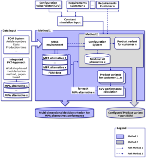
Ein methodisches Vorgehen zur Entwicklung eines konfigurierbaren Modulbaukasten ist schematisch in Abb. ## dargestellt. Das Vorgehen besteht hauptäschlich aus einem Dateneingang und zwei anknüpfenden Methoden. Methode 1 beschreibt dabei die Implementierung von Produktarchitekturen in SysML. Methode 2 beschreibt die Funktionsweise des Konfigurationssystems. Hierbei werden individuelle Produktvarianten auf Basis der verschiedenen Produktarchitekturalternativen erzeugt.

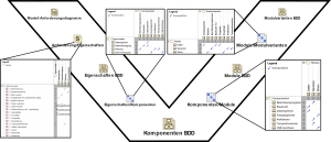
Zur Systemsynthese werden Konfigurationsdiagramme (Configuration Network Diagram) erstellt. Hierbei werden die Produkteigenschaften mit den Komponenten verknüpft und die Komponenten den jeweiligen Modulen zugeordnet. Das ganze kann dann in SysML implementiert werden.

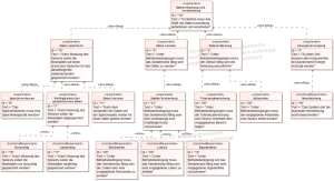
In SysML können separat einzelne Diagramme angefertigt werden, die wie hier zu sehen entlang des V-Modells angeordnet sind. So können verschiedene Diagrammtypen in SysML verwendet werden wie beispielsweise Anforderungs-oder Blockdiagramme, in denen die Produkteigenschaften, Komponenten, Module und Modulvarianten abgebildet werden können. Die einzelnen Diagramme können durch Abhängigkeitsmatrizen verbunden werden. So werden in diesem Fall Anforderungen mit Produkteigenschaften, Eigenschaften mit Komponenten, Komponenten mit Modulen und Module mit Modulvarianten verknüpft. Ein exemplarisches hierarchisches Anforderungsdiagramm ist in Abb. ## dargestellt.

